Product Search
Find the right transformer for your needs
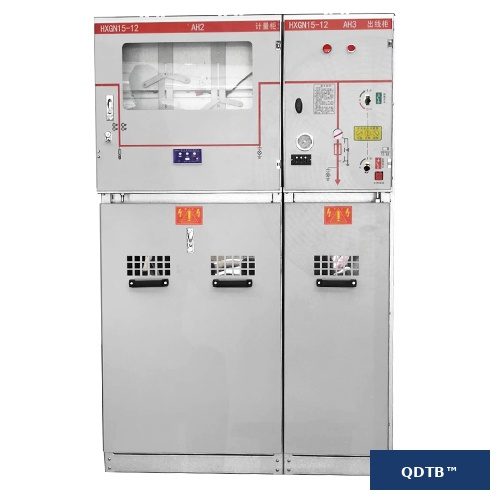
Images are for illustration purposes only
FLN36 Series - Ring Main Units with FTU Integration for Smart Grids
The FLN36 series ring main units with integrated FTU represent the convergence of primary equipment and secondary automation. Factory tested with all protection and monitoring functions pre-configured for fast deployment in distribution networks.
Model Number Breakdown
Applications
Smart grid distribution automation
Urban ring main network monitoring
Industrial power distribution control
Renewable energy integration points
Key Features
- SF6 load break switch with FTU integration
- Primary-secondary fusion in compact design
- Factory pre-commissioned for fast deployment
- Supports smart grid communication protocols
Specifications Range
All specifications and dimensions can be customized upon request
| Key parameters | Model Range |
|---|---|
| Rated Voltage | 12 |
| Rated Current | 630 A |
| Max. Fuse Rating | 63 A |
| Short-time Withstand Current | 20 kA |
| Protection Level | IP4X |
| Standard | GB3906, IEC 62271-200 |
| Compare | Model | Series | Rated voltage (kV) | Current (A) | Frequency (Hz) | Standard | Weight | Dimensions |
|---|---|---|---|---|---|---|---|---|
| FLN36-12D(F) | FLN36 | 12 | 630 | 50 | GB3906, IEC 62271-200 | 700 kg | 1000×800×1800 mm |
Product Drawing
Ring Main Unit - FLN36-12D(F)
Note: This is a general product illustration. For detailed technical drawings and specifications, please contact our engineering team.
Instant Selection & Quote Calculator
Select your specifications to get an estimated price instantly.
More options(3)
Certification
The values below are computed from what you selected above. Anything that cannot be computed yet is shown as an em dash — never as zero.
Iₙ = S / (√3·U) · I_sc = 100·Iₙ / uₖ · S_sc = √3·U·I_sc · I_p = k·Iₖ
Still required to complete the calculation: rated capacity S, impedance voltage uₖ, short-time or peak withstand current.
Per-model values (P0 / Pk / uₖ declared by the factory, losses, noise, temperature rise, dimensions, weight) are not in the product library: those rows stay at an em dash until the factory parameter sheet is supplied. An em dash means the value is unavailable — it is never rendered as zero.
Reference prices are for estimation only and do not constitute a formal offer.
3 · Get this quote
We will reply with your latest quote instantly.
Related Engineering Calculators
Free sizing and pricing tools for this product category.