Product Search
Find the right transformer for your needs
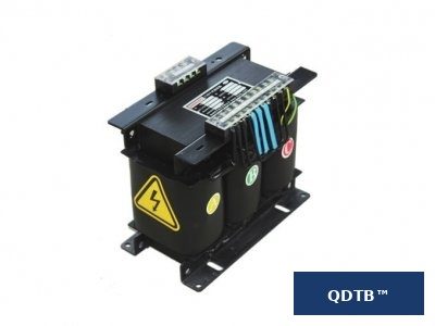
Images are for illustration purposes only
SGK Series - Three Phase Transformers
SGK three-phase isolation transformers provide galvanic isolation for industrial equipment, 5-50 kVA with custom secondary voltages.
Model Number Breakdown
Key Features
- Three-phase galvanic isolation for industrial equipment
- 5-50 kVA with custom secondary voltages
- Suppresses harmonics and transients
- Delta-star or delta-delta configurations
Applications
- Industrial power systems
- Commercial buildings
- Infrastructure projects
TECHNICAL DRAWING
Model: SGK-20KVA | Type: Oil-immersed transformer | Capacity: 20 kVA
FRONT ELEVATION
ELECTRICAL SCHEMATIC
EFFICIENCY vs LOAD
SIDE VIEW
TOP VIEW
TERMINAL BLOCK
CORE & WINDING
LEGEND:
Specifications Range
All specifications and dimensions can be customized upon request
Model Selector
| Key parameters | Model Range |
|---|---|
| Capacity | 5–50 kVA |
| Frequency (Hz) | 50/60 |
| Compare | Model | Series | Capacity (kVA) | Input voltage | Output voltage | Frequency (Hz) | Rated current (A) | Weight | Dimensions |
|---|---|---|---|---|---|---|---|---|---|
| SGK-5KVA | SGK | 5VA | 380V | Custom | 50/60 | 0.01A | 50 kg | 300×175×280 mm | |
| SGK-10KVA | SGK | 10VA | 380V | Custom | 50/60 | 0.02A | 80 kg | 360×185×340 mm | |
| SGK-20KVA | SGK | 20VA | 380V | Custom | 50/60 | 0.03A | 140 kg | 430×215×390 mm | |
| SGK-30KVA | SGK | 30VA | 380V | Custom | 50/60 | 0.05A | 200 kg | 450×270×410 mm | |
| SGK-50KVA | SGK | 50VA | 380V | Custom | 50/60 | 0.08A | 300 kg | 510×300×460 mm |
Instant Selection & Quote Calculator
Select your specifications to get an estimated price instantly.
More options(2)
Certification
The values below are computed from what you selected above. Anything that cannot be computed yet is shown as an em dash — never as zero.
Iₙ = S / (√3·U) · I_sc = 100·Iₙ / uₖ · S_sc = √3·U·I_sc · I_p = k·Iₖ
Still required to complete the calculation: rated capacity S, impedance voltage uₖ, short-time or peak withstand current.
Per-model values (P0 / Pk / uₖ declared by the factory, losses, noise, temperature rise, dimensions, weight) are not in the product library: those rows stay at an em dash until the factory parameter sheet is supplied. An em dash means the value is unavailable — it is never rendered as zero.
Read-only: no price factor, not part of the sum — the loss-grade cost is already carried by the efficiency (subtype) base price, so charging here would double-bill. Values come from the product library type-test data, interpolated between published capacities; grades the library does not cover show an em dash, never zero.
Reference prices are for estimation only and do not constitute a formal offer.
3 · Get this quote
We will reply with your latest quote instantly.
Related Engineering Calculators
Free sizing and pricing tools for this product category.